Objective
The objective of the Smart Parking System project is to revolutionize parking management by leveraging technology to optimize the search for available parking spaces. Through the development of a web application integrated with an SQLite database, the project aims to provide real-time status updates on parking availability, thereby reducing the time and fuel wasted in searching for empty parking spots.
Motivation
The motivation behind the Smart Parking System project stems from the growing challenges associated with multi-story parking management, including congestion, pollution, and wasted time and resources. By harnessing technology to create a smarter and more efficient parking solution, the project aims to alleviate these issues and improve the overall parking experience for drivers. The integration of real-time status updates, sensor technology, and a user-friendly interface underscores the project’s commitment to enhancing convenience, reducing environmental impact, and optimizing resource utilization in urban parking environments.
View Project: Smart Parking System
Architecture Diagram
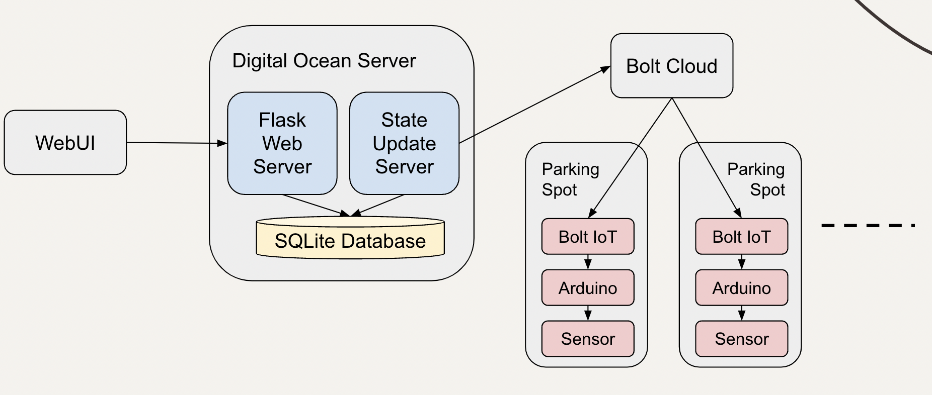
Basic Working
The ultrasonic sensor is used to detect the presence of a car in a parking spot. A sensor is mounted on the ceiling of each parking spot. If a car is not present in the parking spot, the sensor returns the sound wave round trip time from ceiling to floor. The round trip time is lesser when a car is present in the parking spot. The sensor is connected to arduino board which in turn is connected to a bolt module so that we can get the status of each parking spot from the server running in cloud.
An LED is used to indicate an empty parking spot. A driver can easily find an empty spot with the help of glowing LEDs. The LED is connected to a digital output pin in Bolt IoT module so that the LED can be controlled from server through Bolt cloud.
A server running on Digital Ocean is used to periodically get the status of all parking spots and store it in a SQLite database. We run another server to serve web requests for getting free spots on each floor. This information is rendered on a dashboard so that car drivers understand the available free spots on each floor and can quickly drive to the floor with free spots.
Flowchart
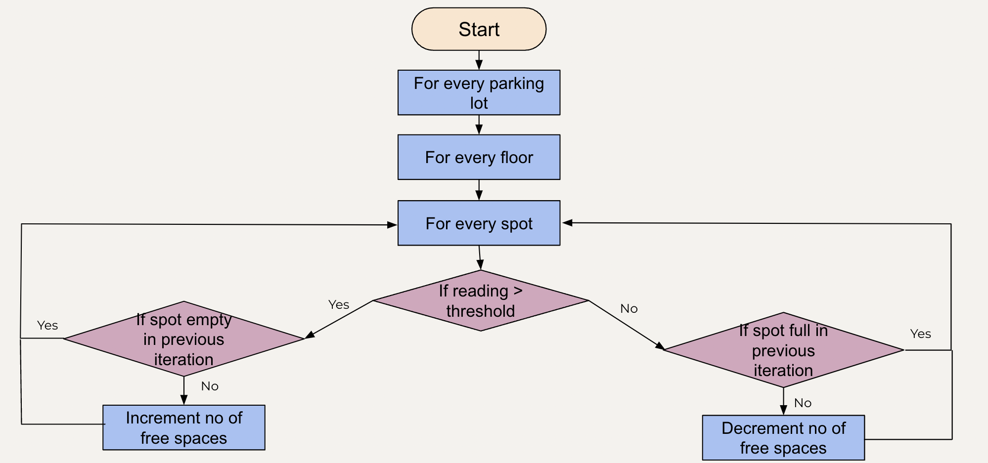
This flowchart shows the working of state update server. It has 3 for loops. The outer for loop is used to iterate through all the parking lots. The second for loop is used to iterate through all the floors present in that parking lot and the innermost for loop is used to iterate through all the spots present on a floor. For every spot we have one ultrasonic sensor. To determine whether a parking spot is empty, we compare the reading of the ultrasonic sensor with the threshold value. Reading greater than the threshold value indicates an absence of car in that spot. In this case, the number of free spaces must be incremented. Before incrementing the number of free spaces, we need to check if the parking spot was full in the previous iteration. Number of free spots is incremented only if that spot was full in the previous iteration.
A reading value lesser than threshold value indicates the presence of a car in the parking spot. In this case, the number of free spaces must be decremented. Before decrementing the number of free spaces, we need to check if the parking spot was empty in the previous iteration. Number of free spots is decremented only if that spot was empty in the previous iteration.
ER Diagram
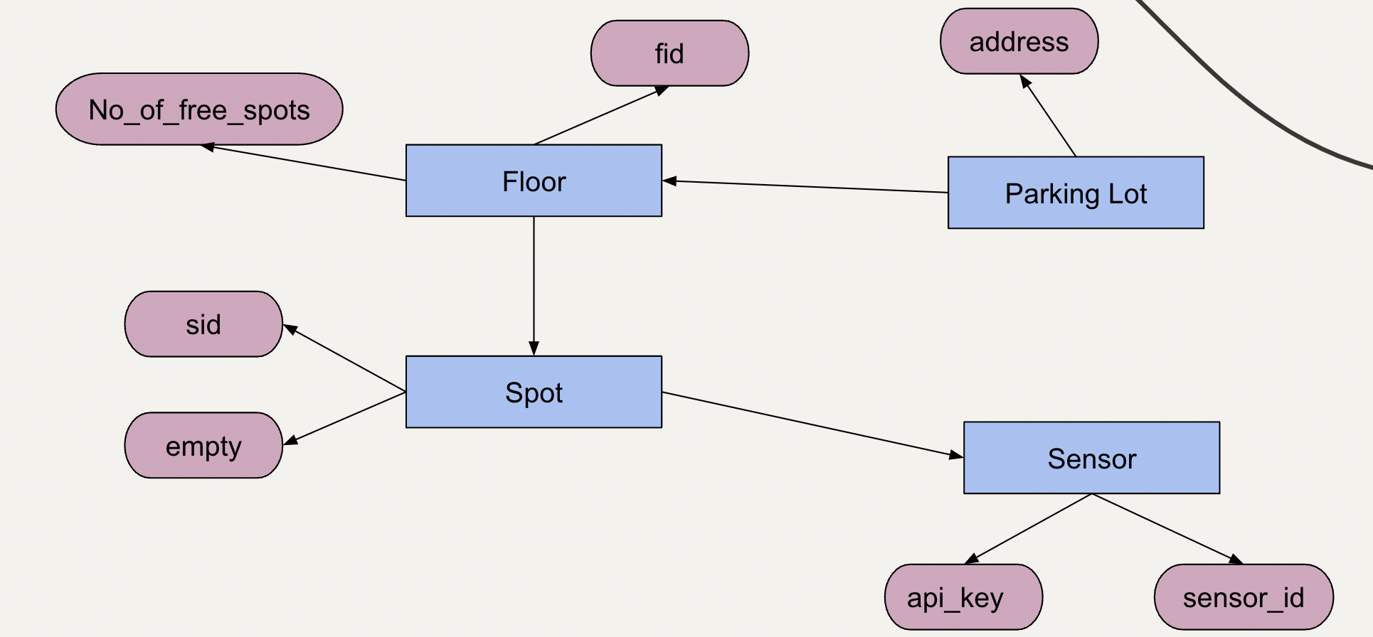
This is an entity relation diagram which explains the relation between the entities of the smart parking system. It has 5 entities namely Parking lot, floor, spot, sensor and bolt cloud. Parking lot has one attribute i.e address which is used to store the location of the parking lot. Parking lot entity has a one to many relationship with the floor entity which indicates that one parking lot can have many floors. The floor entity consists of the floor id-specified by fid- and number of free spots. Floor entity has one to many relationship with spot entity which means one floor has many spots. The spot entity consists of two attributes. The first one is sid which stores the spot id and the second one is empty that takes a boolean value which specifies whether the spot is empty or not. Spot entity has a one to one relationship with sensor which indicates that one spot will have only one sensor. The sensor entity has two attributes - sensor_id which is used to store the id of the bolt module and api key which is used to store the bolt cloud api. The API for all the sensors will be same. This database is used to store the status returned by the bolt cloud.
Message Flow Diagram
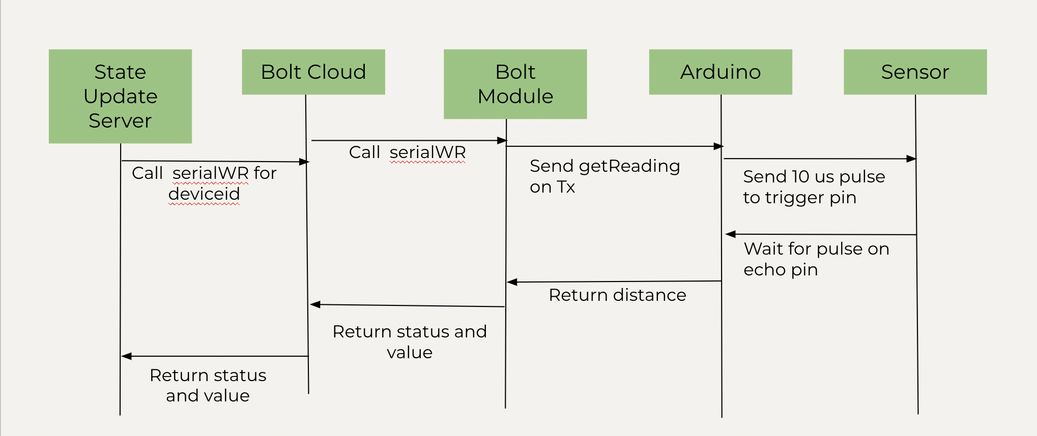
This diagram shows the message flow for getting the status of a parking spot. The state update server calls the serial read-write for device id. The bolt cloud then calls the same function and the bolt module calls get reading function from its Tx i.e transmitting pin for getting the distance reading from the auduino board. Arduino sends a 10 microsecond trigger pulse to the ultrasonic sensor. Sensor then returns the time at which the echo pin sensed the sent trigger pulse to arduino board which then calculates the distance and returns it to the bolt module. Bolt module sends the status i.e whether the query was successful and the value i.e the distance calculated to the bolt cloud and the bolt cloud returns this data to the state update server. This API is called for every parking spot at an interval of 10 seconds.
Circuit Diagram
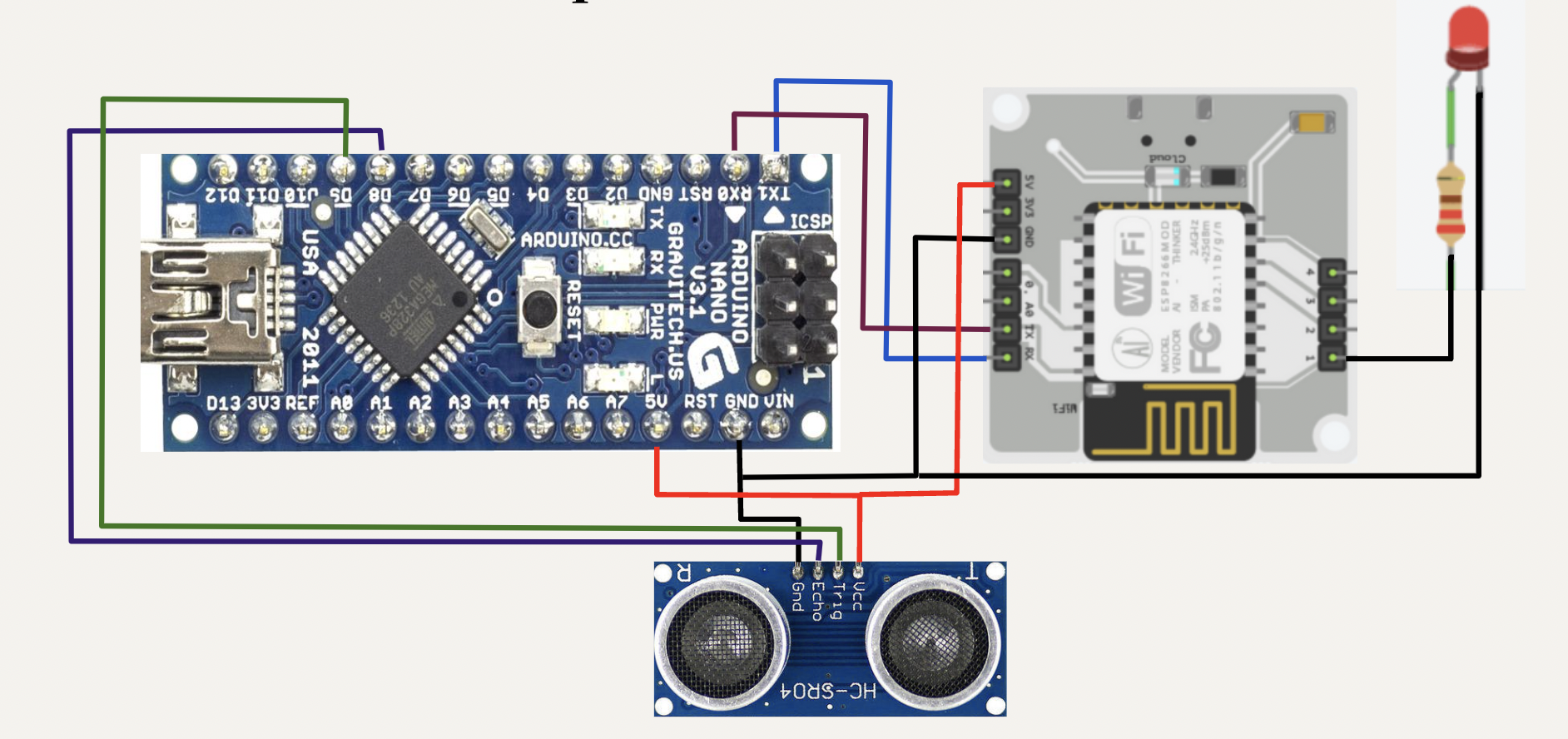
This diagram describes the hardware setup for every parking spot. Arduino Nano is mounted on the bread board. Connect ground pin of bolt module and ultrasonic sensor to ground pin of arduino board. Connect vcc pin of ultrasonic sensor and 5V pin of bolt module to the 5V pin of the arduino board. Connect The echo pin of ultrasonic sensor to digital pin 8 of the arduino board. Connect the trigger pin of the sensor to digital pin 9 of the arduino board. Connect the Tx pin of arduino to Rx pin of the bolt module. Similarly, connect the Rx pin of arduino to Tx pin of bolt module. Connect the negative end of LED to ground and the positive end to a resistor. The other end of resistor is connected to digital pin 1 of the bolt module.
Results
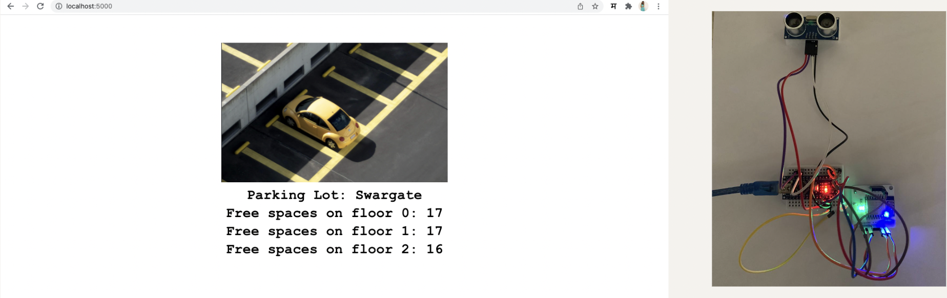
The following image shows the browser output. The LED is ON as the parking spot is empty. Each floor has 17 free spaces.
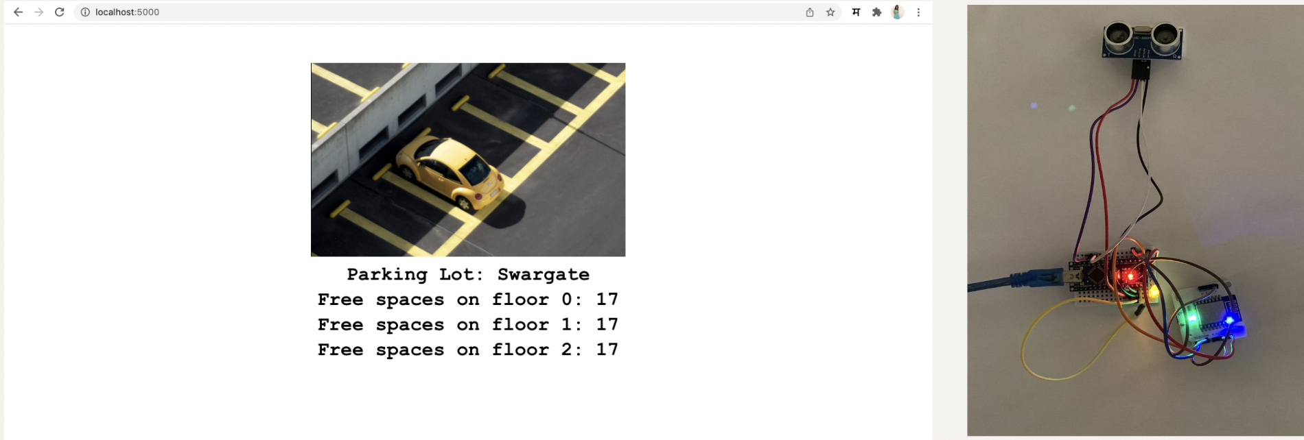
The number of parking spots reduces to 16 and the LED is turned OFF to indicate that the spot is full.